|
Vision Processing for Realtime 3D Data Acquisition Based on Coded Structured Light |
|
S.Y. Chen, Member, IEEE, Y.F. Li, Senior Member, IEEE, and Jianwei Zhang, Member, IEEE |
Abstract?Structured light vision systems have been successfully used for accurate measurement of 3D surfaces in computer vision. However, their applications are mainly limited to scanning stationary objects so far since tens of images have to be captured for recovering one 3D scene. This paper presents an idea for real-time acquisition of 3D surface data by a specially coded vision system. To achieve 3D measurement for a dynamic scene, the data acquisition must be performed with only a single image. A principle of uniquely color-encoded pattern projection is proposed to design a color matrix for improving the reconstruction efficiency. The matrix is produced by a special code sequence and a number of state transitions. A color projector is controlled by a computer to generate the desired color patterns in the scene. The unique indexing of the light codes is crucial here for color projection since it is essential that each light grid be uniquely identified by incorporating local neighborhoods so that 3D reconstruction can be performed with only local analysis of a single image. A scheme is presented to describe such a vision processing method for fast 3D data acquisition. Practical experimental performance is provided to analyze the efficiency of the proposed methods.
Index Terms—real-time measurement, 3D data acquisition, unique code, color-encoded, structured-light, vision sensor, computer vision, robotics, perception
EDICS Categories?/span> HDW-DSGN, STE-STIP, HDW-EMBD, STE-STCD, SDP-SCAN, OTH-OPTI
I. INTRODUCTION
A. Motivation
Computer vision has become a very important means to obtain the three-dimensional (3D) model of an object. A number of 3D sensing methods have been explored by researchers in the past 30 years [1]-[7]. The structured light has made its progress from single light-spot projection to complex coded pattern, and consequently the 3D scanning operation speeds up from several hours per image to dozens of images per second [4] [8] [9].
The first stage of feasible structured light systems came in early 1980 when the binary coding or gray coding methods were employed. Figure 1 illustrates a typical set of light patterns by Inokuchi et al. [10]. This kind of pattern can achieve high accuracy in the measurements [11]-[16]. This is due to the fact that the pattern resolutions are exponentially increasing among the coarse-to-fine light projections and the stripe gap tends to 0, but the stripe locations are easily distinguishable since a small set of primitives is used, and therefore the position of a pixel can be encoded precisely. It also takes the advantage of easy implementation and thus this method is still the most widely used in structured light systems. The main drawback is that they cannot be applied to moving surfaces since multiple patterns must be projected. In order to obtain a better resolution, a technique based on the combination of gray code and phase shifting is often used [11]. Its drawback is that a larger number of projection patterns (e.g. > 20 images) are required.
With the aim to project only one light pattern before capturing a scene image, color stripes are invented for replacing multiple black/white projections. This idea brings a development of “one-shot?3D image acquisition and it is possibly applied in measuring moving objects. People have attempted a lot of such systems for practical implementation [7], [9] [17]-[23], in which a phase-shifting method can also be employed [22]. Among them, the De Bruijn sequences are the mostly used techniques [20] [21]. Although these promise real-time applications, limitations of this method are still considerable. One is its tradeoff between reliability and accuracy. Since adjacent color stripes should have enough spectral difference, people have to use a limited number of color stripes or apply them periodically, which produces either stripe ambiguity or rough resolution. Another limitation is the flexibility of its system setup. Since it is a one-dimensional (1D) spatial coding method, the baseline between the camera and the projector should be nearly orthogonal with light planes. It is suitable for setting up a fixed system, but not for some applications where dynamic reconfiguration and recalibration if multiple degrees of freedom are required.
Two-dimensional (2D) spatial coding has the advantages of windowed image processing and flexible system configuration. The works in the community by Griffin et al [24] and Salvi et al [2] contribute to this technique. In such a coded structured light system, the patterns are specially designed so that codewords are assigned to a set of pixels. As every coded pixel has its own codeword, there is a direct mapping from the codewords to the corresponding coordinates of the pixel in the pattern. To this end, a mathematical study is carried out in [24] (Fig. 2) to determine what should be the largest size allowed for a coded matrix of dot pattern. It is based on several assumptions. First, a dot position is coded with information emitted by itself and the information of its four neighbors. Second, there cannot be two different dot positions with the same code. Third, the information is determined using a fixed basis, which determines the symbols used to code the matrix. Fourth, the biggest matrix is desired, i.e. the matrix which gives a better resolution. The codewords are simply numbers, which are mapped in the pattern by using grey levels, color [2] or geometrical representations [24]. However, these special geometrical shapes or color lines have to be placed separately for them to be detected in an image (Fig. 3). Otherwise, the uncertainty in real scene would make this detection very difficult due to noise, distortion, and discontinuity. In fact, the adjacent shapes or lines should be different and placed on each other with direct contact, as formulated in this paper later.
In order to gain flexibility during the acquisition process, adaptive techniques can be used. Researchers have investigated some active stereo systems that can adapt the color of the projected pattern to tackle the problem of light reflections generated by the scanned objects [1] [3] [25]. An interesting work is carried out by Koninckx etc. [26]. They propose a real-time scanner that can adapt itself to the scene. It aims to generate better patterns online by taking the properties of scene and setup into account. The code lines are generated according to epipolar geometry (Fig. 4). A weighted combination of different coding cues yields a robust way to solve the correspondence problem. The system, however, is a little complex as it requires predicting, labeling, and tracking scene features. An assumption is also based on temporal continuity between subsequent frames. Regarding codification, a single code line, as explained on the other hand, poses too much of a risk to go undetected in large parts of the image. More vertical code-lines generate a higher code-density, but the decoding becomes worse conditioned. Thus a tracking algorithm has to be involved.
In this paper, we propose a new idea in designing a grid solid pattern for 3D reconstruction with fast matching strategies. Based on this idea, the system combines the advantages of real-time, low-cost, reliable, and accurate 3D data acquisition. The steps for vision processing, including color codification, pattern rendering, word seeding and flood searching, mesh amendment, and 3D computation are investigated in the paper. Efficiency analysis and experimental implementation are also reported in following sections.
Figure 1. A typical gray-coding method [10] (1984)
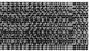
Figure 2. The pattern designed by Griffin et al [24] (1992)
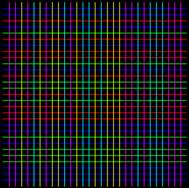
Figure 3. The pattern designed by Salvi et al [2] (2004)
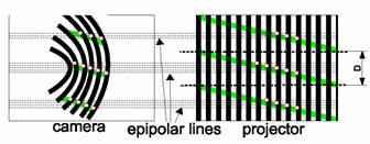
Figure 4. Adaptive light projection by Koninckx et al [26] (2006)
II. Color Codification
A. A Color-Coded Structured Light System
The structured light system in this work consists of a CCD camera and a digital projector (Fig. 5). That is similar to the traditional stereo vision system, but with its second camera replaced by the light source which projects a known pattern of light on the scene. Another single camera captures the illuminated scene. The required 3D information can be obtained by analyzing the deformation of the imaged pattern with respect to the projected one. Here the correspondences between the projected pattern and the imaged one can be solved directly via codifying the projected pattern, so that each projected light point carries some information. When the point is imaged on the image plane, this information can be used to determine its coordinates on the projected pattern.
 |
Figure 5. Sensor structure for color-coded vision
B. Grid-Pattern Coding Requirements
Different from the case of the stripe light vision system where the coordinates on the projector can be determined by analyzing the bit-plane stack obtained from multiple images, the coordinates in the color projection vision system have to be determined in a single image. In an effort to avoid the drawbacks of the traditional coding techniques, we attempt to improve the projected light pattern since a practical system has to consider more application requirements.
A method is developed for designing the grid patterns that can meet the practical requirements of uniquely indexing for solving uncertain occlusions and discontinuities in the scene. Let P be a set of color primitives, P={1,2,? p} (where the numbers {1,2,? p} representing different colors, e.g. 1=white, 2=red, 3=green, 4=blue, etc.). These color primitives are assigned to an m?/span>n matrix M to form the encoded pattern which may be projected onto the scene. We define a word from M by the color value at location (i, j) in M and the color values of its 4-adjacent neighbors. If xij is the assigned color point at row i and column j in M, then the word for defining this location, wij, is the sequence { xij, xi,j-1, xi-1,j, xij+1, xi+1,j} where i?/span>{1, 2, ? m} and j?/span>{1, 2, ? n}, i.e. wij is a substring as following
![]() ? (1)
? (1)
If a lookup table is maintained for all of the word values in M, then each word defines a location in M. Then we can know that an m?/span>n matrix M has (m-1)?/span>(n-1) words. These words are made up of a set W. We need to assign the color primitives of P to the matrix M so that there are no two identical words in the matrix, i.e.
Condition 1:  ?2)
?2)
Furthermore, every element has a color different from its adjacent neighbors in the word, i.e.
Condition 2: ![]() (3)
(3)
In this way, each defined location is uniquely indexed and thus correspondence will be of no problem. That is, if the pattern is projected onto a scene, and the word value for an imaged point (u, v) is determined (by determining the colors of that imaged point and its 4-adjacent neighbors), then the corresponding position (i, j) in M of this imaged point is uniquely defined. Of course, in addition to having each word of M be unique, we also wish to optimize the color code assignments so that matrix M is as large as possible.
A problem should be considered in the assignment. Because there are only three primary colors, the color pattern should be divided into several distinguishable color codes. To reduce the complexity of identifying color codes of a grid point among its neighbors, every two color codes should have enough distance. This requires a tradeoff between the number of color codes and the average code distance. The white color should be utilized mostly for segmentation of neighbor grid points so that the pattern will produce maximum image irradiance values.
According to the perspective transformation principle, the image coordinates and the assigned code words of a spatial point are correspondent to its world coordinates. We can establish such a mapping relation between an image point in the image coordinate system and the spatial point in the world coordinate system. X, Y, and Z are the coordinates of a world point, corresponding with the image coordinates u, v and x, y. Together with the system calibration parameters, the 3D information of the surface points can be easily computed. Effectively, it can guarantee that the measurement system has a limited cost of computation since it only needs to analyze a small part of the scene and identify the coordinates by local image processing. Therefore the acquisition efficiency is greatly improved.
C. Pattern Codification
First, with a given color set P, we try to make a longest horizontal code sequence,
![]() ?4)
?4)
where m is the sequence length. For any adjacent color pair, it satisfies
![]() ?5)
?5)
and any triplet of adjacent colors, T3i = [ci? ci+1?ci+2], is unique in the sequence,
![]() ?6)
?6)
The maximal length of the horizontal sequence Sh is:
Length(Sh) = p(p-1)(p-1)+2. ?(7)
This is obvious, since for p colors, the maximal number of independent triplets is p(p-1)(p-1). Suppose all of them can be linked together, and the chain length is p(p-1)(p-1)+2. Practical deduction also proved that this chain length is always attainable.
Since analytical solution to derive such a horizontal sequence is complex, it can be generated by a random-search algorithm instead. In this work, we tested with all color numbers less than 32 and every color set can generate a chain with its maximum length in a few seconds or minutes. The execution time for 7 colors is 0.2 seconds to generate a chain with 254 digits. The time for 15 colors is 25 seconds for a 2942-length chain. The time for 32 colors is about 5 minutes to generate a 30754-chain (no practical vision system requires so much codes actually). The searching time increases exponentially with the number of colors. It is, however, generated offline only once and will not affect the real-time performance. Therefore no much attention was paid to improving the searching algorithm. Furthermore, a 1024-length horizontal chain is enough for common grid-color coding since the projector resolution is limited. Usually we need a grid size with at least 5x5 square.
Second, with a given color set P, we try to make a color state transition sequence (STS), which will be used to derive the color sequence from one row to a new one,
![]() ?8)
?8)
where n is the sequence length. For any adjacent color pair, it does not need to satisfy condition (5), but has to ensure its uniqueness in the sequence,
![]() ?9)
?9)
With unique adjacent state pairs, one can get an STS with the longest Length(Ss) = (s-1)2 +1 in the following way:
Ss = [1 1 2 1 3 1 4 ...1 s, 2 2 3 2 4 ...2 s, ..., (s-1) s, s 1] (10)
The sequence Ss in (10) satisfies (9) and all its pairs are unique in the sequence. In fact, the first part of the sequence [1 1 2 1 3 1 4 ...1 s] contains all pairs within a 1 except for [s 1]. It has 2(s-1)+1 digits and each pair is unique. The second part contains all unique pairs within a 2 and this part adds extra 2(s-2)+1 digits. In this way, adding a 1 at the end of the sequence, we find that each pair in the sequence is unique.
For p colors, the available states to change is one less than it, i.e. s = p-1. Finally, the matrix for color projection can be generated by the longest STS and a maximal horizontal sequence (Ss and Sh). This produces a matrix with the size of (p-1)2+2 by p(p-1)2+2 which is the maximum possible size for each codeword being unique in the matrix. The first row in the matrix can be defined by Sh. A second row is created by adding the first element of Ss to each element of Sh modulo p, where the modulo operation is only on the set {1, 2 . . . . . p} and does not include the 0 element as does the traditional modulo operation. Then we can create a third row by adding the second element of Ss to each element of its above row modulo p. In this way, for a 4-color set the construction is an 11?/span>38 matrix. If it is defined as M = Sh ?/span> Ss, it can be proved that according to definition (1) each word in the matrix S is uniquely located.
The above-mentioned method generates a special code matrix which satisfies conditions (2) and (3). This generation scheme is a finite automata: after the first row is defined, a following row is generated by a number of transitions jumped from its row above. However, this scheme has the drawback that the matrix has a “long band? shape which is sometimes not what we want. For example, a 4-color set generates an 11?/span>38 matrix, a 5-color set generates an 18?/span>82 matrix, a 6-color set generates a 27?/span>152 matrix, etc. The practical digital projector usually has an image with 4:3 or 16:9 for width:height. Therefore, we desire to generate a matrix like that shape or a square. On solution is to generate a very large matrix and we only cut a part of it to fit the practical projector, but this wastes many color codes. On the other hand, while it is still difficult to mathematically generate such matrices by a formulation, this paper solve this by computer simulation. A program is developed to find a maximum square matrix using a random-search algorithm. Examples of the generated grid patterns are given in the next subsection.
D. Examples of Grid Patterns
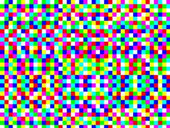
Figure 6. A 38?/span>212 tessellated pattern rendered from a 7-color set
In case that a color set contains four different colors, a matrix can be formulated by the generation scheme, M = Sh ?/span> Ss, which generates an 11?/span>38 coded pattern. Practically, however, we usually need a square pattern to output to a digital projector, and thus a matrix of only 11?/span>11 can be utilized. Using the random-search algorithm, it found the maximum square matrix of a 4-color set is with size of 18?/span>18.
To increase the matrix size so that the digital projector will project a light pattern with better resolution, we have to increase the color number. In our laboratory, a set with 7 colors is often used, which can generate a matrix for a 38?/span>212 rectangle or an 82?/span>82 square. Figure 6 illustrates the light pattern with each grid size = 20?/span>20 pixels.
When such a coded matrix is projected by a digital color projector, each word in the pattern can be found with its unique coordinates from an image.
III. Processing for 3D Reconstruction
A. Initial Seed Words
For 3D reconstruction, an important step is to find a unique word (initial seed) in an unknown area of the acquired image. This can be implemented in the following way. First, randomly generate a position in the image or in the WOI. The color at this position should not be BLACK. Simply judge it by a logical function
![]() ? (11)
? (11)
where r, g, and b are the three color components of the sampled point, Tb is a black threshold, Is is a small neighbor area of the concerned point, gray(x) is the function to convert color to gray value, and count(x) is the number of pixels of an area.
Then, find the square grid point at that position. A color similarity measurement (12) is used to search a quadrangle in which colors are changing slightly compared with those outside.
![]() ? (12)
? (12)
where c1 and c2 are two color values, re, ge, and be are related coefficients obtained from color calibration. The grid point is set to be the centroid of this quadrangle.
Based on this grid point, we try to locate its four adjacent neighbors. Simply set the offset to be the grid-size estimated, the left, right, above, and nether points are initialized and the four square areas are determined. If this grid point is found not in a regular shape, or any one of the four neighbors failed to be located, another initial position should be generated. Finally, the coordinates of the seed word are determined according to the five grid points by corresponding their color codes in the pattern matrix.
B. Flood Search for Word Identification
With the known grid size and initial seed word, it is easy to find all adjacent words by a flood search algorithm [27][28]. It firstly tries to search several grid points around the seed word, and then search more grid points near the known area. Each point to be added in the known partial net has to satisfy three conditions ?its color, size, and regularity.
The color measured in the image is often not ideal as what should be due to the distortion in the vision system and scene reflection. Besides the color calibration strategies to be discussed later, we can determine it by a color likelihood function. The image pixel is compared with all the seven ideal colors in the coding set. If the desired code color corresponds to one of the three largest likelihood values, the grid point is accepted in the net.
Since it is a “one-pass? method, i.e. the pixels are computed only in a small local area once, the image processing can be performed very fast, promising real-time applications. The speed evaluation will be analyzed in the next section for performance analysis and also in the experiment section.
C. Mesh Amendment and Interpolation
The mesh amendment and grid interpolation procedures are developed in this paper for optimization of 3D results. The projection of the coded pattern should result in a regular mesh. However, due to the complexity of the scene and uncertainty in image processing, the constructed grid matrix could have some faults (namely holes and leaves). To correct these faults, this research develops a Mesh Amendment Procedure to find and amend them. For some cases, it can decide directly whether “insertion?or “deletion?is necessary to amend the net (as illustrated in Fig. 7 and Fig. 8). Under a few other conditions, such an operation has to be determined according to its actual image content and with a likelihood measurement (Fig. 9).

Figure 7. Cases of mesh amendment for holes (insertion)
Figure 8. Cases of mesh amendment for leaves (deletion)

Figure 9. Decision based on content likelihood measurement
After all possible code words have been identified from the image, it is easy to compute the 3D world coordinates of these points since the coordinates on both the image (xc, yc) and the projector (xp, yp) are known. This yields a rough 3D map of the scene. In order to improve the resolution, we may perform an interpolation algorithm on such map. Depending on the application requirements, the interpolation may be only on the segment of two adjacent grid points or inside the square area formed by four regular grid points.
IV. Performance Analysis
This section provides theoretical analysis of the time complexity for obtaining a 3D image so that we may select better strategies to implement for real-time applications. There are many image operations in the above-mentioned procedure for 3D surface construction. To simplify the analysis but without loss of much precision, in this paper the elemental arithmetic operators of the machine processor are assumed to contain only operations equivalent to add and multiply. Equivalent add operations are such like addition, subtraction, comparison, assignment, and logical operations. Equivalent multiply operations are such like multiplication, division, and square operations. Assume that an equivalent add costs a time complexity of Cadd and an equivalent multiply costs complexity of Cmul. The main steps that affect the online speed for 3D image acquisition are analyzed below.
A. The Cost to Identify One Grid Point
Assume that a grid point in the image has a rough size of u?/span>v. To locate and identify the area of such a grid point, we need to do the following steps:
1) Pointing to the location of a grid point
To locate to a new grid point, since the rough position is generated by the flood searching algorithm or generated with seeds, this step is simply to copy the coordinates in the image. The cost is equivalently equal to four additions:
tp1 = 4Cadd.
2) Measurement of Color Likelihood
To determine if the candidate position is admissible in the sense of color pattern satisfaction, the color likelihood is measured. The cost is equivalent to
tp2 = 2Cmul +?3(1Cmul + 4Cadd).
3) Square Area Determination
Suppose that we need to evaluate every pixel inside the square area of a grid point. The computation complexity is mainly occupied by (12):
tp3 = 2uv [4Cmul + 5Cadd]
where the square root function was eliminated since practically it is not necessary to perform it.
In fact, the optimization can be carried out to evaluate only some pixels near the four boundaries for a practical system. That will greatly reduce the computation complexity.
4) Centroid of the Square Area
The complexity for determining the centroid of a square area can be estimated as:
tp4 = 2uv [2Cmul + 2Cadd] + 2Cmul
If for reason of speed, this centroid estimation can also be given with a rather low cost, i.e. to simply determine it according to the four boundaries. Then it is nearly
top4 = 6Cadd
In total, the computation cost without optimization is about
Cp = tp1 + tp2 + tp3 + tp4
= 12uvCmul + 14uvCadd + 7Cmul + 12Cadd ?(13)
It is obvious that the computation complexity is dominated by the first part, i.e. O(Cp) = O(12uvCmul). Therefore, the time cost for identification of a grid point in the image can be estimated as
TP = 12uvTmul. (14)
where Tmul is the average time for an equivalent multiply operation of the machine processor.
B. The Cost for Flood Search throughout an Image
For an image of size m?/span>n, the time cost of flood search to identify all possible grid points is
![]() ? ?15)
? ?15)
where CF is the time complexity for constructing the searching mesh and it can be estimated as
![]() ? ?(16)
? ?(16)
Here we assumed that each point is visited two times during the flood search. In fact, there are many algorithms proposed to visit each point with only one time [27][28]. This paper would not adopt these best strategies, but only roughly estimate the possibility for real-time application and leave more optimization opportunities for engineering implementation.
Combining (13) with (16), we get
![]() ? ?(17)
? ?(17)
The time cost for flood search over the whole image can be estimated as
T5 = 12mnTmul. (18)
C. Summary of Costs for the Whole Procedure
Based on the above analysis, we can further estimate the time cost for mesh amendment to be
![]() (19)
(19)
where cmatch is a coefficient reflecting the matching complexity in pattern comparison between the constructed image mesh and the amendment pattern list (here cmatch = 49 for those as in Fig. 7-9).?Tadd is the average time for an equivalent add operation by the processor.
We can see that the time cost for computation of 3D coordinates, T7, is mainly to solve a linear system as formulated similarly with stereo vision:
X = (ATA)-1ATB (20)
where X = [x, y, z] is the world coordinates of a specific point in the scene, the matrices A with size 4?/span>3 and B with size 4?/span>1 are constructed directly from the calibration matrices, coordinates (xc, yc) and (xp, yp). Then T7 can be estimated to be
![]() ?(21)
?(21)
For computing the 3D mesh, we can choose to do it from either the original image data with formula (20) or simply interpolating 3D coordinates of known grid points in T6 step. The former can give better accuracy but low efficiency, as compared to be
![]() ?(22)
?(22)
![]()
![]() (23)
(23)
That means that the latter runs about eight times as fast as for direct computation from original image data.
Now consider the construction of the 3D surface from the whole image. Similar to compute for the 3D mesh, it can also be processed with two ways:
![]() (24)
(24)
![]() ?
?(25)
?
?(25)
It can also be eight times faster for a complete 3D surface when only interpolating from 3D grid points.
Table I summarizes the relative time costs of these main functions for acquisition of a 3D image from the vision system. Practical verification is carried out in experimental studies and will be presented in the next section.
TABLE I. Relative Time Complexity of Some Main Processing Functions for Image Analysis and 3D Reconstruction
|
|
Function |
Theoretical time |
|
T4 |
locating a seed word |
5Tp=60uvTmul |
|
T5 |
Flood search for all grids |
12mnTmul |
|
T6 |
Mesh amendment |
98mnTadd/uv |
|
T7 |
3D computation of mesh grid points |
16mnTmul/uv |
|
T8 |
3D wire shape |
T8a = (u + v)T7 T8b = T8a/8 |
|
T9 |
Interpolation or computation for the full 3D surface |
T9a = uvT7 T9b = T9a/8 |
V. Experiments
A. Example of Implementation
To implement the idea in a practical vision system and analyze the performance, we have to consider many other factors and conditions. In fact, this method has to be integrated with other techniques and algorithms for automating the modeling process, such as system calibration, image processing, 3D representation, and visualization. Thanks to considerable fundamental works on computer vision developed in our early projects [29], the experimental system is convenient to reset up for this purpose.
The vision system in our laboratory includes a structured light sensor set up with a projector and a camera. The projector is a palm-sized digital projector with 2000:1 contrast and 1.2-11.8 m working distance. It is connected to a computer and is controlled to generate the color encoded patterns for 3D reconstruction. The CCD camera (PULNIX TMC-9700) has a 1-inch sensor and a 16 mm lens. A 32-Bit PCI Frame Grabber for machine vision by Coreco Imaging Co. Ltd., PC2-Vision, is used to capture live images in 640?/span>480 size. The main computer is a common PC, with a 2.1GHz CPU and 512MB RAM, for image processing and 3D computation.
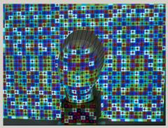
Figure 10. An image captured from the scene where illuminated by a uniquely encoded light pattern. A random position is generated to find a seed word for flood search. Net amendment is performed to deal with some unfilled holes and abnomal leaves. In the example, total three seeds were generated automatically one by one to get the final mesh due to surface discontinuty.
In the experiments, a 44?/span>212 encoded pattern generated from a 7-color set (Fig. 6) is used to illuminate the scene. The grid size is 25?/span>25 pixels. Figure 10 illustrates an image captured by the camera, in which there are about 30 * 37 = 1110 grid points. A seed word is identified randomly in the image. Then grid points are detected by a flood-search algorithm. Repeating the work until no large area is possible to yield more points, the whole net will be merged from them. The amended mesh after detecting isolated holes and abnormal leaves is also illustrated in Fig. 10. Finally, the 3D mesh was reconstructed after performing 3D computation and a typical example is illustrated in Fig. 11.
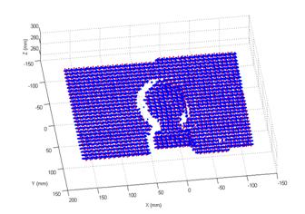
Figure 11. After 3D reconstruction
B. Observation of Efficiency
To observe the execution performance and evaluate the efficiency of each function in the vision system, this paper used the Performance Analyzer (a program development tool) to check the time spent in some important procedures. For a common PC nowadays with a 2GHz CPU, a typical float multiply operation takes several to tens nanoseconds (ns). If an additional floating point co-processor is integrated, it can be done below 1 ns. Here if we, with a little conservation, assume a typical multiplication takes 10 ns and a typical addition takes 1 ns, the theoretical time and practical time measured in our lab is listed in Table II. It can be seen that for 3D reconstruction in low-level or mid-level resolution (only computing the 3D coordinates on grid points or grid edges), it takes 70 to 100 ms (T10 and T11). That speed is adequate for most applications. Although theoretically the speed can be achieved to about 38 ms, we currently have some break points for debugging in the program that affect some efficiency.
TABLE II. Analysis of Execution Performance
|
|
Function |
Theoretical time |
Actual time |
Remark |
|
T0 |
Pattern Coding |
seconds-minutes |
NA |
Done offline |
|
T1 |
Light projection |
17 ms (first frame) 0 ms (new frames) |
0 |
Pattern is never changed |
|
T2 |
Image acquisition |
Dependent on imaging device hardware |
25 ms |
For image freezing |
|
T3 |
Memory allocation, movement |
Dependent on the computer |
0.3 ms |
Can be faster when using high speed cache |
|
T4 |
locating a seed word |
60uvTmul @135us |
0.1 ms |
|
|
T5 |
Flood search for all grid points |
12mnTmul @36.864ms |
44 ms |
|
|
T6 |
Mesh amendment |
98mnTadd/uv @133.8us |
0.1ms |
|
|
T7 |
3D computation of grid points |
16mnTmul/uv @218.45us |
3 ms |
|
|
T8 |
3D wire shape |
T8a = (u+ v)T7 @6.55ms T8b = T8a/8 @819.19us |
32 ms |
Measured for T8a |
|
T9 |
full 3D surface |
T9a = uvT7 @49.15ms T9b = T9a/8 @6.14ms |
85 ms |
Measured for T9a |
|
T10 |
3D imaging with low-resolution |
37.35ms |
72.5 ms |
T1+T2+T3+T4 +T5+T6+T7 |
|
T11 |
3D imaging with mid-resolution |
43.90ms / 38.17ms |
104.5 ms |
T8+T10 |
|
T12 |
3D imaging with high-resolution |
86.50ms / 43.49ms |
157.5 ms |
T9+T10 |
1 ns = 10-3 us = 10-6 ms = 10-9 second.
Theoretical time is calculated when u=v=15, m=640,n=480, Tmul=10ns.
Furthermore, by applying the speed optimization as proposed in Section IV, we can estimate that the processing efficiency can be further improved by 30% to 50%. More possible opportunities still exist to optimize for real-time use. Furthermore, the time for imaging in Table II can also be eliminated since image freezing and image processing can be made in parallel. Then the speed is limited to the bigger number. With good engineering skills for system implementation in both software and hardware, it will not be difficult to achieve the speed of about 30 frames per second (fps) for the 3D imaging system.
VI. Discussion
A. Efficiency
The proposed method is based on a specially coded pattern projection which allows the 3D vision processing to be performed locally. The coding scheme assures real-time processing in three aspects: (a) we may choose only the region of interest in the image to be reconstructed, (b) image processing is performed locally in a one-word area, (c) we may choose to reconstruct the 3D surface in a high, middle, or low resolution according to practical situations (to reconstruct a surface in lower resolution according to hardware limitation and processor speed).
The efficiency is analyzed by both theoretical computation complexity and experimental observation. Although practical experiments coincide well with the analytical estimations, the computing time depends on many factors, e.g. segmentation complexity, surface color appearance, block size, image distortion, chip speed, caches/buffers, memory access speed, operating system, thread load, etc.
For comparison with a few other good results reported, Koninckx et al. [26] reported that the frame rates varying between 10 and 25 fps, dependent on scene complexity. Zhang & Huang [22] implies that the scanning speed would be varying between 26-240 fps according practical hardware and software conditions. Tsalakanidou et al. [23] deliver 17-25 fps. Our method has no obvious advantage over theirs on the aspect of processing speed, but our proposed scheme has the advantages of reliability (every word is independent), hardware reconfiguration (relative pose between the camera and projector is not restricted and even dynamically adjustable), flexibility (selectable resolution and color sets), etc.
B. Accuracy
Although the 3D computation is briefly discussed above, no metrological evaluation is given in the paper yet. In fact, the accuracy or precision of the proposed system is similar to other typical structured light systems since the triangulation is based on the same geometry. The best accuracy of those systems using stripe light projection (without phase-shifting) is expected to be achievable in this system, but all factors that affect the accuracy in common structured light systems will also result in some errors. The experiments in this paper were carried out with a typical system setup. In fact, the accuracy of dimensional measurement is dependent on many factors (e.g. the length of baseline, image resolution, projector resolution, object distance, calibration accuracy, surface orientation, etc.), but affected less by the vision processing method. To estimate the measurement precision in detail, some previous works on structured light can be referred to [8] [15] [20] [31]-[34]. For example, Sansoni etc. [15] analyzed the systematic errors dependent on the baseline length d, object distance L, and imaging angle a.
From these contributions, we know that the metrological sensitivity is mainly on its system structure. In this paper, the baseline is about 200 mm, the object distance is about 350 mm, the projection angle is about 20 degrees, and the image resolution is about 640x480. Since we didn’t perform a very careful calibration before it is used for 3D data acquisition, the observed error is about 2% relatively on some specific line segments in the scene. The accuracy can be raised greatly by some engineering skills, e.g. about 0.01% as in [23].
System calibration errors will directly introduce measurement errors [8], and thus careful calibration should be performed for an engineering system. Legarda-Saenz et al. [31] and Vargas et al. [34] give us a detailed description of an accurate procedure to calibrate the structured light system. Methodology for error estimation can also be found in [33].
If the spatial resolution does not meet the requirement of measurement precision, a sub-pixel strategy may be employed for improvement [7][20]. When the image resolution increases, however, more processing time is required accordingly.
C. Engineering Implementation
1) Color calibration and color transformation
In the above deduction, the system requires that the sensor has a uniform spectral response; that is, the intensity of the red, green, and blue signals are comparable. To achieve this, a calibration procedure should be performed. Wust et al. [18] use a flat plane of the same color as that of the surface to be measured to sample standard colors for rectifying these responsive curves.
Sometimes color space transformation, performed to use intensity, hue, and saturation instead of RGB values, is helpful to improve image segmentation and word identification. However, this introduces some extra computational load and it can be applied only when processing time is not critical.
2) Hardware and Software
The hardware setup can also be implemented something like that in the patent [9] for practical cost consideration. Instead of using a digital projector, the one replaced by a common light source together with a transparent (grass or plastic) plate will greatly cut down the hardware cost (even cheaper than a common stereo vision setup). This, however, reduces the flexibility of the 3D imaging system since light pattern can not be dynamically changed according to scene conditions.
Parallel computation can also be considered if we need a high-speed 3D imaging system. Since the proposed method is based on local processing, this can be implemented without much difficulty.
In general, this paper did not adopt the best strategies in many issues, but only focuses on the estimation of the possibility for real-time application and leave more optimization opportunities for engineering implementation.
VII. Conclusion
Real-time, low-cost, reliable, and accurate 3D data acquisition is a dream for us in the vision community. While the available technology is still not able to reach all these features together, this paper makes a significant progress to the goal. An idea was presented and implemented for generating a specially color-coded light pattern, which combines the advantages of both fast 3D vision processing from a single image and reliability and accuracy from the principle of structured light systems. With a given set of color primitives, the patterns generated are guaranteed to be a large matrix and desired shape with the restriction that each word in the pattern matrix must be unique. By using such a light pattern, correspondence is solved within a single image and therefore this is used in a dynamic environment for real-time applications. Furthermore, the method does not have a limit in the smoothness of object surfaces since it only requires analyzing a small part of the scene and identifies the coordinates by local image processing, which greatly improves the 3D reconstruction efficiency. Theoretical analysis and experimental results show that acquisition of a 3D surface with mid-level resolution takes about 100 ms which is adequate for many practical applications. Some software and hardware skills may be applied to further improve the speed to above 30 frames per second (fps). A parallel processing scheme will further increases the efficiency several times.
References
[1] M. Ribo and M. Brandner. ?/span>State of the art on vision-based structured light systems for 3d measurements? IEEE Int. Workshop on Robotic Sensors: Robotic and Sensor Environments, Ottawa, Canada, pp. 2-, Sep. 20057.
[2] J. Salvi, J. Pags, J. Batlle. ?/span>Pattern Codification Strategies in Structured Light Systems? Pattern Recognition 37(4) , pp. 827-849, April 2004.
[3] D. Desjardins, P. Payeur, "Dense Stereo Range Sensing with Marching Pseudo-Random Patterns", 4th Canadian Conf. on Computer and Robot Vision, pp. 216 - 226, May 2007.
[4] F. Blais, ?/span>Review of 20 Years of Range Sensor Development?/span> J. of Electronic Imaging, 13(1) , pp. 231-240, 2004.
[5] S. Osawa, etc., ?-D Shape Measurement by Self-referenced Pattern Projection Method? Measurement, Vol. 26, pp. 157-166, 1999.
[6] C.S. Chen, Y.P. Hung, C.C. Chiang, J.L. Wu, Range, “Data Acquisition Using Color Structured lighting and Stereo Vision? Image and Vision Computing, Vol. 15, pp. 445-456, 1997.
[7] L. Zhang, B. Curless, S. M. Seitz, “Rapid Shape Acquisition Using Color Structured Light and Multi-pass Dynamic Programming? IEEE Proc. on 3D Data Processing Visualization and Transmission, Padova, Italy, pp. 24-36, June?2002.
[8] Li, Y. F. and Chen, S. Y., "Automatic Recalibration of an Active Structured Light Vision System", IEEE Trans. on Robotics and Automation, Vol. 19, No.2, pp. 259-268, April 2003.
[9] T. Lu, J. Zhang, "Three dimensional imaging system", United States Patent 6252623, June 26, 2001.
[10] S. Inokuchi, K. Sato, and F. Matsuda, "Range-imaging system for 3-D object recognition", 7th Int. Conf. Pattern Recognition, Montreal, Canada, pp. 806-808, 1984.
[11] J.Gühring, “Dense 3-D surface acquisition by structured light using off-the shelf components? Videometrics and optical Methods for 3D Shape Measurement, vol. 4309, pp.200-231, 2001.
[12] W. Krattenthaler, K. J. Mayer, etc., ?D-surface measurement with coded light approach,?4th Int. Workshop for Digital Image Processing and Computer Graphics, Oldenburg, Germany, Vol. 12, pp. 103?14, 1993.
[13] S, Rusinkiewicz , O. Hall-Holt , M. Levoy, "Real-Time 3D Model Acquisition", ACM Trans. on Graphics, Vol. 21, No.3, pp. 438-446, 2002.
[14] P. Vuylsteke and A. Oosterlinck, "Range Image Acquisition with a Single Binary-Encoded Light Pattern", IEEE Trans. on Pattern Analysis and Machine Intelligence 12(2) , pp. 148-164, 1990.
[15] G. Sansoni, M. Carocci, R. Rodella, ?/span>Three-Dimensional Vision Based on a Combination of Gray-Code and Phase-Shift Light Projection: Analysis and Compensation of the Systematic Errors?/span>, Applied Optics, Vol. 38, Issue 31, pp. 6565-6573, 1999.
[16] M. Young, E. Beeson, etc., ?/span>Viewpoint-Coded Structured Light? IEEE Computer Society Conf. on Computer Vision and Pattern Recognition (CVPR), Minneapolis, Minnesota, June 2007.
[17] E. Schubert, H. Rath, and J. Klicker, "Fast 3D Object Recognition Using a Combination of Color-Coded Phase-Shift Principle and Colour-Coded Triangulation," SPIE, vol. 2247, pp. 202-213, 1994.
[18] C. Wust and D.W. Capson. "Surface Profile Measurement Using Color Fringe Projection," Machine Vision and Applications, 4, 1991, pp. 193-203.
[19] K.L. Boyer and A.C. Kak, "Color-encoded structured light for rapid active ranging," IEEE Trans. on Pattern Analysis and Machine Intelligence, vol. 9, 1987, pp. 14-28.
[20] H. Li, R. Straub, and H. Prautzsch, "Structured Light Based Reconstruction Under Local Spatial Coherence Assumption", 3rd IEEE Int. Symp. on 3D Data Processing, Visualization and Transmission, Washington, DC, USA, pp. 575-582, June 2006.
[21] J. Pages, J. Salvi, etc., ?/span>Optimised De Bruijn patterns for one-shot shape acquisition? Image and Vision Computing, 23(8) , pp.707-720, 2005.
[22] S. Zhang; P. Huang, "High-Resolution, Real-time 3D Shape Acquisition," 2004 Conf. on Computer Vision and Pattern Recognition Workshop, pp. 28- 28, June 2004.
[23] F. Tsalakanidou, etc. "Real-time acquisition of depth and color images using structured light and its application to 3D face recognition", Real-Time Imaging, Vol. 11, No. 5-6, pp.358-369, Dec. 2005.
[24] P.M.Griffn, L.S.Narasimhan, S.R.Yee, “Generation of uniquely encoded light patterns for range data acquisition? Pattern Recognition, 25(6), pp. 609-616, 1992.
[25] R. Furukawa, H. Kawasaki, "Dense 3D Reconstruction with an Uncalibrated Stereo System using Coded Structured Light", IEEE Computer Society Conf. on Computer Vision and Pattern Recognition, pp. 107 - 107, June 2005.
[26] T. P. Koninckx, L. V. Gool, "Real-Time Range Acquisition by Adaptive Structured Light," IEEE Trans. on Pattern Analysis and Machine Intelligence, vol. 28, no. 3, pp. 432-445, March 2006.
[27] A. Glassner, "Fill 'er up! [Graphics filling algorithms]", IEEE Computer Graphics and Applications, Vol.21, No.1, pp. 78 - 85, Jan. 2001.
[28] Anton Treuenfels, ?/span>An Efficient Flood Visit Algorithm? C/C++ Users Journal, Vol.12, No. 8, Aug. 1994. http:// www.cuj.com
[29] S. Y. Chen and Y. F. Li, "Vision Sensor Planning for 3-D Model Acquisition", IEEE Trans. on Systems, Man and Cybernetics, Part B, Vol. 35, No. 5, pp. 894-904, Oct. 2005.
[30] C. Sinlapeecheewa and K. Takamasu, "3D profile measurement using color multi-line stripe pattern with one shot scanning", Integrated Computer-Aided Engineering, Vol. 12, pp. 333?41, 2005.
[31] R. Legarda-Saenz, T. Bothe, and W. P. Jüptner, "Accurate Procedure for the Calibration of a Structured Light System," Opt. Eng. 43, 2004, pp. 464-471.
[32] Z.J. Geng, "Rainbow Three-Dimensional Camera: New Concept of High-Speed Three-dimensional Vision Systems," Optical Engineering, vol. 35, pp. 376-383, 1996.
[33] J.-A. Beraldin, M. Rioux, etc., ?/span>Traceable 3D Imaging Metrology? Videometrics IX - SPIE Electronic Imaging 2007, Vol. 6491, pp. B.1-B.11, 2007.
[34] J. Vargas, J. A. Quiroga, and M. J. Terron-Lopez, "Flexible calibration procedure for fringe projection profilometry", Optical Engineering, Vol. 46, pp. 023601, Feb. 2007.
S. Y. Chen (M?1) received the Ph.D. degree in computer vision from the Department of Manufacturing Engineering and Engineering Management, City University of Hong Kong, Hong Kong, in 2003.
He joined Zhejiang University of Technology, China, in Feb. 2004 where he is currently an Associate Professor in the Department of Information Engineering. Since July 2004, he has been invited as a guest researcher in the National Laboratory of Pattern Recognition, Institute of Automation, Chinese Academy of Sciences. From Aug. 2006 to Aug. 2007, he received a fellowship from the Alexander von Humboldt Foundation of Germany and works in the Dept of Informatics, University of Hamburg, Germany. His research interests include computer vision, robotics, 3-D object modeling, and medical image analysis.
Dr. Chen is a committee member of IEE/IET Shanghai Branch. He has published over 50 papers in important international journals and conferences. He received the Research Award of Fok-Ying-Tung Education Foundation by Ministry of Education of China in 2006, was awarded as the Champion in 2003 IEEE Region 10 Student Paper Competition, and was nominated as a finalist candidate for 2004 Hong Kong Young Scientist Award.
Y. F. Li (M?1–SM?1) received the Ph.D. degree in robotics from the Department of Engineering Science, University of Oxford, Oxford, U.K., in 1993.
From 1993 to 1995, he was a Postdoctoral Research Associate in the Department of Computer Science, University of Wales, Aberystwyth, U.K. He joined City University of Hong Kong, Hong Kong, in 1995 where he is currently an Associate Professor in the Department of Manufacturing Engineering and Engineering Management. His research interests include robot vision, sensing, and sensor-based control for robotics. In these areas, he has published over 100 papers in international journals and conferences. He is an associate editor of IEEE Transactions on Automation Science and Engineering (T-ASE).
Jianwei Zhang (M?2) received the Ph.D. degree in informatics from University of Karlsruhe, Germany, in 1994.
From 1994 to 2002, he was an Associate Professor and Full Professor in the Technical Informatics Group, University of Bielefeld, Germany. He joined University of Hamburg in 2002 where he is currently a Full Professor (C4) and Director at the Institute of Technical Multimodal Systems in the Department of Informatics. He has authored more than 100 journal and conference papers and received the IEEE ROMAN Award in 2002. His research interests include robot learning, cognitive interface, intelligent signal processing, and neuro-fuzzy systems.