|
Intelligent Lighting Control for Vision-Based Robotic Manipulation |
|
S.Y. Chen, Senior Member, IEEE, and?Jianwei Zhang, Member, IEEE, Houxiang Zhang, Member, IEEE, N.M. Kwok, Member, IEEE, Y.F. Li, Senior Member, IEEE |
Abstract?/span>The ability of a robot vision system to capture informative images is greatly affected by the condition of lighting in the scene. This work reveals the importance of active lighting control for robotic manipulation and proposes novel strategies for good visual interpretation of objects in the workspace. Good illumination means that it helps to get images with large signal-to-noise ratio, wide range of linearity, high image contrast, and true color rendering of the object’s natural properties. It should also avoid occurrences of highlight and extreme intensity unbalance. If only passive illumination is used, the robot often gets poor images where no appropriate algorithms can be used to extract useful information. A fuzzy controller is further developed to maintain the lighting level suitable for robotic manipulation and guidance in dynamic environments. As carried out in this research, with both examples of numerical simulations and practical experiments, it promises satisfactory results with the proposed idea of active lighting control.
Index Terms?/span>robot intelligence, active vision, active lighting control, illumination planning, computer vision, perception, fuzzy control
I. INTRODUCTION
|
T |
he lighting technology for robot vision has been appealed by some researchers in the community of industrial electronics for image acquisition and manufacturing applications [1]-[4], but its importance is still far under-estimated nowadays, especially in the aspect of automatic lighting control [5]. The new trend in industrial automation requires lighting to play an active role. Traditional methods for robot vision to better interpret scenes usually focus on image post-processing (e.g. smoothing, filtering, masking, zooming, contrast stretching, pseudocoloring, debluring, or even super-resolution processing) [6]. However, post-processing does not increase the inherent information content. It is a matter of fact that an originally good image contains more information of object surfaces. This facilitates further vision analysis and saves time-consuming enhancement processing, which is very important in a robotic system, especially for real-time applications [7]-[9]. The principal reasons for success in machine vision are the elimination of appearance variations and the consistent appearance that appropriate, application-specific lighting yields [10].
For many machine-vision applications, lighting now is one of the most challenging considerations in system design, and becomes a major factor when it comes to implementing color inspection [11] [12]. The uniformity and the stability of the incoming lighting are usually the common causes of unsatisfactory and unreliable performance of machine-vision systems. As with any light, illumination has the properties of intensity and color, which significantly affect the performance of robot vision perception as well as human perception [13].
The effort made by Eltoft and de Figueiredo is one of the earliest important attempts in lighting control [14], and there are other literature also addressing this problem [15]. Later on, researchers have become more aware of this issue [16]-[18]. Their work discusses many factors of illumination conditions that affect the quality of the image. The evaluation criteria of lighting conditions should be quantitatively given [19].
Apart from the apparent structure and working mechanism, a camera in the robotic vision system works very similar to a human eye with some comparable characteristics like resolution, bandwidth, luminosity, and color [18]. A lot of camera series are ready for practical use, where most of them can be modeled with a set of parameters, such as focal length, imager size, resolution, angle of view, etc., for vision acquisition planning [20]. Although many cameras now provide some functions of automate exposure, automate gain control, and automate white balance, in a lot of practical applications of machine vision the cameras should be implemented with the fixed or digitally controlled focuses and apertures for reasons of reliable measurement. In another aspect, Ortiz and Oliver provided a method for radiometric calibration which contained an algorithm for characterizing the noise sources affecting CCD performance with the aim of estimating the uncertainty of the intensity values yielded by vision cameras [21]. Srinivasa et al. used a temporal dithering method for changing the brightness values [22]. However, the problem is still open for robots working in dynamic environments [23].
This paper combines the vision perception with lighting control. It addresses the question of how we can implement an adaptive strategy for achieving good illumination conditions in a vision system. We begin with an analysis of the robotic vision environment. Attributes for good quality images are formulated and the motivation for intelligent lighting control is further consolidated. The fuzzy controller is adopted in this paper as an effective way to incorporate human experience into lighting control of robotic systems.
II. Lighting Conditions in Robotics
A. Vision in Robotic Environment
Fig. 1 Lighting conditions in a robotic system
The lighting condition in a robotic system is often very complicated and the acquisition of a good vision perception is sometimes inevitably difficult due to the lack of effective illumination. This is also a major reason that the vision system has not been widely applied in practice because it is sometimes unreliable, or actually mostly unreliable. If the image quality can be assured, the vision performance can be greatly improved. Figure 1 illustrates the working situation in a robotic system.
B. Rating of Image Quality
Here are some quantitative criteria to evaluate the quality of an image in certain vision tasks. These criteria include signal-to-noise ratio (SNR), linearity, contrast, and natural properties of the object. First, SNR is one of the image fidelity criteria which is an important factor in considering illumination control. A higher SNR produces a picture with enhanced sharpness or other desirable attributes.
Second, linearity is another important factor because a typical vision sensor has a limited dynamic range of intensity sensitivity. That is, the image irradiance should lie in a linear intensity range otherwise some information is compressed or lost [24]. Usually it has good linearity between 5% and 85% of the maximum gray level.
Third, original contrast is important in vision processing because it means that clear surface information could be obtained. Although contrast can also be enhanced during post-processing of the acquired images, original contrast must be high enough so that it survives in the quantization process.
Finally, we should also address the problem of feature enhancement. The features of interest include the geometrical object shape and surface optical properties, which are both represented through reflective responsity and the color vector [25]. Therefore, another purpose of illumination control for feature enhancement is to improve the contrast of reflective responsity and render the true color of the object surface. To this purpose, we need to carefully control the luminaire pose, radiant intensity, and color temperature.
III. Formulation for Lighting Control
A. Estimation of Image Irradiance
To obtain good visual results from the robot cameras, apart from selecting proper types of light source and cameras, the key controllable parameters of a light source are radiant intensity and geometrical pose in a practical vision system. The purpose of lighting control is to achieve proper image brightness which is in the range of the sensor, with linear property, and has the contrast as high as possible. The purpose of pose control is to avoid any possible highlights and achieve uniform intensity distribution, as well as adjustment of image irradiance.
To maintain the image intensity around an optimal point, firstly the sensor sensitivity must be considered, then the image irradiance is estimated from source radiation to image sensing, and finally the optimal control point is determined.
The brightness that the camera perceives is the light intensity and varies depending on the color of the light. The intensity distribution is quantified by a curve of the brightness sensation versus wavelength, called the luminosity curve. For a color camera, the sensor's spectral response is expressed in three luminosity curves.
To estimate the image irradiance, we need to analyze these steps in the whole procedure, i.e. source radiation, source efficiency, surface irradiance, surface reflection, and sensor perception. First, the total output radiation of a light source at temperature T is found in proportion to the fourth power of the temperature. According to Planck’s radiation law, the spectral distribution of the radiation emitted by a blackbody can be described as a function of wavelength l.
Consider that the vision sensor is sensitive only to a portion of the electro-magnetic wave, i.e. 380<l<750 (nm). Due to the quantum efficiency of the vision sensor, the quantity of light as seen by the camera is, the luminous flux to the image can be estimated as [19]
![]() ?sub>
?sub>![]() . ?(1)
. ?(1)
where C1 and C2 are radiation constants and C(T) is a the coefficient function
![]() (2)
(2)
When a numerical computation method is used to solve (2), a functional curve is obtained. The luminous flux function in (1) is solved to estimate the image intensity. It is thus known that the relationship between the image brightness and the light source temperature is related to the input energy. Moreover, the light source temperature is directly controllable by the current or voltage supply of the electrical power, Uf and If. This relationship can be given as
![]() . ?(3)
. ?(3)
where T0 = 293.15K and m1 is a constant related to the specific light source.
On the other hand, the resistance of an adjustable light source is nonlinear. It is also related to the source temperature and actually increasing with increasing current and voltage.
rs = asT + bs. (4)
Therefore, equation (3) can be rewritten for directly relating the temperature and supply voltage
![]() . (5)
. (5)
Nevertheless, the light emitted by a source is usually not uniformly distributed in all directions and the luminous intensity varies according to the position beneath the source. Manufacturers of luminaires usually provide intensity distribution diagrams for their products, which show the relationship between the luminous intensity and the angle to a reference position of 0o situated vertically below the source. The polar graph is often used for these purposes. It can also be calibrated using the techniques of luminaire photometry developed by Lewin and John [26][27]. Then the effective energy distribution can be modeled as, L(f, q)=Wrgb G(f, q), where the function 0?/span>G(f, q)<1 describes the spatial distribution of source radiation.
Considering a point on the object surface, its irradiance is the integral of the whole angular distribution over a specified solid angle. The object surface then becomes another source and the image irradiance of the vision sensor can also be computed. For each pixel in the image, its intensity is inversely proportional to the square of the distance between the light source and object surface (DL) if all other conditions, like surface normal, viewing direction, camera focus, and aperture, etc. Therefore, we have
![]() . ?(6)
. ?(6)
where K(x, y) is the coefficient related to a pixel’s spatial position and the geometrical relationship.
Since real objects are usually not Lambertians, there are three elements contribute to the surface reflection; namely, diffuse reflection Id, gross specular reflection Is1, and specular reflection Is2. The image irradiance of an object illuminated by a source is represented by a function as in [28].
From (1) and (6), we can find how the image brightness is related to the properties of a light source. The model of the lighting curve can establish the relationship between the controlling parameters (input current, the position and orientation of the light source) and controlling goal (image intensity).
B. Control of Image Intensity
According to the aforementioned formulation, we should further investigate the desired image intensity for control of a practical robotic system. The minimum light input cannot be too small due to the dark current performance of the CCD cells. A camera usually has the requirement of minimum illumination. On the other hand, a brighter scene may bring higher SNR because it contains a larger signal with the same noise and higher image contrast.
Fig. 2?The image linearity and the good control setpoint
The vision sensor often has best linearity between 15% and 90% of the output level (Fig. 2). In fact, the illumination condition below 20% is not good because: 1) low SNR for the existence of noise and dark current, 2) nonlinear quantization in this area, 3) nonlinearity because of gamma correction. An illumination condition above 90% output level is also unacceptable because of contrast compression of the knee slope and loss of color properties. Experienced from practical implementation, a good setpoint of image intensity is between 50-85% of the overflow level because of high SNR, linearity, and contrast.
The lighting level can be controlled in three ways: 1) phase-control to adjust the electrical current intensity using a dimmer; 2) optics-control to adjust the camera aperture or shutter; and 3) pose-control to adjust the distance between object and luminaire using a robot end-effector. Usually it is better to keep the luminaires far away from the object because the illumination will be more uniform in this case and will increase image SNR. It is also better to keep the luminaire in the fully-on state because it entails a higher color rending index in this condition and facilitates the acquisition of true surface information.
Therefore, robot vision applications have a desperate need for feedback control. The vision-illumination system can be considered a closed-loop system in which the vision sensor plays a secondary role as the feedback channel. The pose and dimmer phase are determined by a controller according to the visual feedback, source model, and optimal setpoint. The energy magnitude of source radiation and image irradiance may be estimated using the techniques discussed above.
IV. Design of the Lighting Control System
A typical system for illumination control usually includes a robot, manipulators of light source and vision sensors, an image processor, a system controller, and an object in the scene. Here we focus on the control of the energy magnitude of source radiation, although other parameters may be considered in future. The goal of the control system is to keep the sensed object in a good illumination condition so that it will be beneficial to further modeling processes.
Fig. 3?Block diagram of illumination control
The block diagram of the illumination control system is illustrated in Fig. 3. The right-top part is for vision processing, the right-bottom part is for control of the robotic system, and the left part is for light fusion. The symbol xe is the disturbance of the environment. It results from three causes: the changing natural light, the dynamic environment, and the moving vision sensor; xo is the sensed image (the output of vision preprocessing). xr is the image irradiance after the displacement of the vision sensor and the illuminants. s is a vector of robotic parameters, the output value for setting the vision sensor's parameters and illuminant's parameters. Ke is the gain which relates the image irradiance and the parameters of both vision sensor and illuminant (geometrical pose and optical settings). The vision system and robot system can be considered as that they only introduce some unit delays, e.g. V(z)=kv/zn and R(z)=kr/zm. V(z) is for image processing and understanding and R(z) is for robotic mechanism and lighting adjustment. The controller C(z) can be developed in various ways, either traditional deterministic controllers or other robust and intelligent controllers. Its role is to satisfy the above-mentioned constraints and keep the image from becoming too dark or too bright. The control parameters are based on image irradiance distribution, a statistical value or vector based on the image histogram.
In principle, there are many methods that can be used for designing the controller, e.g. genetic algorithms and neural networks. This paper has attempted some preliminary experiments using a proportional-integral-differential (PID) controller that worked occasionally for the robotic systems if purely for intensity control. However, it is always difficult to find the optimal controller parameters which have to be changed according to the scene conditions, e.g. the properties among the object, the camera, and the light source. Genetic algorithm and neural network can not take any advantages either. Due to the knowledge of the underlying process, it is found that the fuzzy logic is most favorable because it has the advantage that the solution can be cast in terms that human operators can understand and their experience can be used in the design of the controller. There are many input and output variables in the controller and there are many issues have to be addressed in practical systems. Fuzzy logic makes the control strategy easier to mechanize tasks that are already intuitively performed by humans in their successful instances. It is also more flexible to adjust fuzzy inference rules when the control strategy has to be changed among different robotic systems.
The radiant intensity of the light source can be adjusted by the electric current using a dimmer for phase control. The simplest way is to generate a Pulse Width Modulation (PWM) signal and compare the message signal to a triangular or ramp waveform [29][30].
V. Fuzzy Controller
Consider the nonlinear, complex, and ill-conditioned natures of the control system. This paper employees a fuzzy control method, for its proven performance and easy incorporation of human experience, as the most suitable controller design methodology in active lighting system. Key issues that play important roles in the current problem are described below.
A. Choice of Controller Input
The most natural and frequently used inputs for the fuzzy controller are the image intensity and its distribution. In order to simplify the design, three kinds of parameters derived from the image are considered, i.e. the average intensity of the overall image Iave, the average intensity in the region of interest (ROI) Iroi, and the distributional unbalance over the whole image Idis.
The overall average intensity Iave is simply determined by averaging the intensity of all pixels in the image. That is, Iave = N-1SSIij, where N is the number of pixels. We expect that most pixel intensities, giving the image brightness, is located near the “good?position as indicated in Fig. 3, i.e. it should not be dark, somewhat bright but below the knee point. Therefore, the fuzzy membership of Iave is designed and depicted in Fig. 5. There are three membership functions, namely, “Dark? “Good? and “Bright?curves, covering the universe of discourse. The exact membership function values are set by calibrating a number of the camera responses, or just set to some empirical numbers, e.g. L=30, B=200, hb=215, H=230, F=255. Although empirical values of membership functions usually give a good control action, in order to improve the performance, some feedback tuning or self-tuning methods (e.g. [31][32]) may be used to tune the membership functions of the input variables. In particular, the support of membership function “Good?only covers up to a value of H where it is the contrast compression knee where the highlight slope starts. The asymmetric form of fuzzification in Fig. 4 can assure the image intensity to be control at a relatively bright level but still in a linear range of the camera curve.
Fig. 4?Fuzzification of image intensity Iave and Iroi.
 ?img
width=205 height=185 src="tie12lighting.files/image012.jpg">
?img
width=205 height=185 src="tie12lighting.files/image012.jpg">
? (a) ?(b)
Fig. 5?Image balance control. (a) The positions of image blocks for computing the distributional unbalance. (b) Fuzzification of distributional unbalance {Idis}
The whole input image is uniformly divided into 9 blocks, Bij, 1 ?/span> i, j ?/span> 3. Suppose that both the camera and the light source have the mechanism of reposition. We assume that the ROI is always located in the image center because it benefits image processing. The center area of an image also has less projection distortion. If only the light source can be replaced, we can not guarantee the ROI in the center. The related program should be changed accordingly in this case, but it can still be dealt with the similar strategies. Therefore, by the assumption that the ROI is always located in the center area of the image, it is represented by the block BROI in Fig. 5a. As the appearances of highlight should be avoided within the ROI, the parameter Iroi is computed by averaging the intensities of pixels which are above the median intensity of all pixels inside the ROI block. That is, Iroi = Sbi, bi?/span>BROI and bi ?/span>median(BROI). The fuzzy membership of ROI intensity Iroi is defined similarly as Iave in Fig. 4.
Lighting with uniform spatial distribution is the most efficient solution for an illuminating scene to be captured by a vision system. If the intensity distribution is non-uniform and the pattern is uncalibrated, it will become an additional source of noise and the SNR is degraded. An image balance metric is therefore used in the design of the controller in order to mitigate information lost in the image.
Beside the region of interest BROI, there are other eight blocks defined for computing the distributional unbalance over the whole image Idis. Figure 5a illustrates the positions of these blocks according to their sub-image placements. As illustrated in Fig. 5b, nine membership functions are defined, i.e. WN, NN, NE, WW, OO, EE, WS, SS, and SE. The corresponding input variables are converted from the image blocks by the following equations.
fWN = ![]() /1020.
/1020.
fNN = ![]() /1020.
/1020.
fWW = ![]() /1020.
/1020.
fNE = ![]() /1020.
/1020.
fOO = ![]() /1020.
/1020.
fSE = - fWN
fSS = - fNN
fEE = - fWW
fWS = - fNE
where IB represents the mean pixel intensity in a block B as illustrated in Fig. 5a. The sum is divided by 4?/span>255=1020 to normalize the variable in [-1, 1]. These variables are mapped in Fig. 5b to find the corresponding fuzzy memberships.
In addition to the image cues as the input of fuzzy control, we also need to consider some other information for achieving better controlling results, such as the current voltage U, the light source orientation (fL, qL), the lighting distance DL, etc.
The voltage U directly controls the source temperature and lighting energy as defined in (1) and (5). It is expected that the light source always works in either of two operation states where it should be either “Off?or somewhat normal “Bright? It should avoid such situation that the light is “On?but very dark. Otherwise it affects not only the efficiency from electricity to light energy conversion, but also the bad color temperature which causes non-uniform response of natural properties of object surfaces. Therefore, the fuzzy membership of voltage U is designed as in Fig. 6a. There are three membership functions. Function “Full?means that the light is turned to its maximum illumination capability (e.g. 24.0V). Function “On?means the light source is working in the controllable range and “Off?means that its voltage is set very low and should be fully switched off. The membership support Vl should be set according to specific light sources or determined by an empirical value, e.g. 50% of maximum voltage.
(a)
(b)
(c)
(d)
Fig. 6?Fuzzification of input variables. (a) voltage U, (b) light source orientation (f, q), (c) light source distance DL, (d) diameter of lens aperture fc.
The light source orientation (fL, qL) is used to decrease the image unbalance effect. We have to make use of the light energy distribution, as defined in (6), and actual mechanical setup to control the orientation. Some robotic systems implement two degrees of freedom (2DOF) for independent control of the light source. The fuzzy functions of fL and qL are mainly used to keep image balance. The two variables should be located in their practical ranges, i.e. f?/span>[fmin, fmax] and q?/span>[qmin, qmax]. Figure 6b illustrates the fuzzy memberships of a simplified mechanical model, e.g. qL,fL?/span>[-15o, 15o].
The lighting distance DL is used to adjust the image brightness and uniform attribute. The light intensity is inversely proportional to DL2 as defined in (6). On the other hand, DL can also affect the light distribution in the scene. A large distance is usually better in the system, but it reduces the energy efficiency. The fuzzy function is not very critical for DL. Figure 6c gives a typical design and the relevant Dmin, Dm, and Dmax parameters can be assigned according to the light type and empirical numbers.
The diameter of lens aperture fc is sometimes controllable in some vision systems, but it has to be kept in a range so that it will not cause much image blur. The image intensity is proportional to the square of the aperture diameter, i.e. I(x, y) ?/span> fc2. Both very small and very large fc should be avoided for the reason of image quality. Its fuzzy function is not very critical. Figure 6d gives a typical design and the relevant fcmin, fcm, and fcmax parameters can be assigned according to the lens type and empirically.
B. Decision Strategies
There are three control objectives while considering the decision strategies, i.e.
Objective 1 ?To maintain the image brightness in a good range. A good setpoint of image level can be taken according to the curve illustrated in Fig. 3.
Objective 2 ?To avoid highlight appearing in the scene ROI which is assumed always in the center area of the image.
Objective 3 ?To keep the whole image in a good status of brightness balance.
To implement the lighting control system, many practical issues have to be considered for getting good performance. As there are many variables that may be used to adjust the image brightness (the light source position and orientation, the lighting level, the camera orientation and imaging distance, the focus, the aperture diameter, the geometric normal and physical material of the object surface, etc.), this paper sets out several control priorities for robot behaviors and vision conditions.
Priority level 1 - Electrical Parameters (e.g. voltage U). Pure electrical variables are assigned to the highest priority due to control efficiency and easy realization. In this case, therefore, only the voltage U is adjusted if it can be realized to keep the image in a good condition. It usually does not cause any correlated effects if no optical and mechanical parameters are changed.
Priority level 2 - Optical Parameters (e.g. f and fc). The optical parameters are controllable only in some special system setups, e.g. with digital controllable cameras. These parameters are also constrained with some other factors, e.g. target distance and camera calibration. The camera has to be recalibrated when its parameters are changed. Some vision systems usually employ a self-calibration algorithm for this purpose.
Priority level 3 - Mechanical Parameters (e.g. fL, q L, and DL). It is most complex to change the mechanical parameters in a robot system due to operation efficiency, manipulation complexity, energy consumption, workspace, and mechanical reachability or environmental collision, safety, and other robot tasks conducted in parallel.
With consideration of these strategies and priority levels, an interference table is used to make decisions for fuzzy control. As listed in Table I, there are some setup conditions in the first column, i.e.
- Light source dimmer. The rules are applicable when a digital dimmer is available for the robot to control the lighting volume.
- Light source reposition. The rules are applicable when the distance between the light source and object surface is controllable.
- Controllable aperture. The rules are applicable when the diameter of lens aperture is digitally controllable.
- Camera reposition. The rules are applicable when both the camera is movable and the lens aperture is digitally controllable.
- Light source orientation. The rules are applicable when there are two additional degrees of freedom in the robotic mechanism and available for independent control.
Table I?Decision for active lighting control
|
Setup |
(Input, Status, Priority) |
Output |
|
Light source Dimmer |
(Iave, Dark, r2) |
DU, Positive |
|
(Iroi, Good, r1) |
DU, Zero |
|
|
(Iave, Bright, r2) |
DU, Negative |
|
|
(Iroi, Bright, r1) |
DU, Negative |
|
|
Light source Reposition |
(Iroi, Bright, r5)&(U, Off, 1) |
DL, Dmax |
|
(Iroi, Dark, 1)&(U, Full, 1) |
DL, Dm |
|
|
Controllable aperture |
(Iave, Dark, 1) |
Dfc, Positive |
|
(Iave, Bright, 1) |
Dfc, Negative |
|
|
(Iroi, Good, 1) |
Dfc, Zero |
|
|
(Iroi, Bright, r3)&(U, Off, 1) |
Dfc, Negative |
|
|
(Iroi, Dark, r3)&(U, Full, 1) |
Dfc, Positive |
|
|
Camera reposition |
(Iave, Dark, 1) |
DDc, Negative |
|
(Iave, Bright, 1) |
DDc, Positive |
|
|
(Iroi, Good, 1) |
DDc, Zero |
|
|
(Iroi, Bright, r4)&(U, Off, 1) |
DDc, Positive |
|
|
(Iroi, Dark, r4)&(U, Full, 1) |
DDc, Negative |
|
|
Light source Orientation |
(Idis, OO, r6) |
(DfL, 0), (Dq L, 0) |
|
(Idis, WN, r6) |
(DfLi + Dq Lj, SE) |
|
|
(Idis, NN, r6) |
(DfLi + Dq Lj, SS) |
|
|
(Idis, NE, r6) |
(DfLi + Dq Lj, WS) |
|
|
(Idis, WW, r6) |
(DfLi + Dq Lj, EE) |
|
|
(Idis, EE, r6) |
(DfLi + Dq Lj, WW) |
|
|
(Idis, WS, r6) |
(DfLi + Dq Lj, NE) |
|
|
(Idis, SS, r6) |
(DfLi + Dq Lj, NN) |
|
|
(Idis, SE, r6) |
(DfLi + Dq Lj, WN) |
The second and third column contains some rules for fuzzy decision in the robotic vision system. The “IF?part is combined with one or two triplets, defined as (Input, Status, Priority), which checks the status of each input variable of the controller. The priority coefficients are set to improve the robot manipulation performance. There are six coefficients defined in this paper, i.e. r1?/span> r2?/span> r3?/span> r4?/span> r5?/span> r6. Here we give a typical parameter set like [r1, r2, r3, r4, r5, r6]=[2.0, 1.0, 0.6, 0.4, 0.2, 0.2]. It is not essential and is often given empirically, but will affect the robot performance to some extent. The “THEN?part of the rules includes the output variables and their desired changes of the controller. More details are given in the next subsection. Table I is a condensed form. Only important rules of three membership functions are included. For practical implementation, it has to be expanded into a regular one. Each rule may be associated with a weight according to the priority.
C. Output for Robotic Manipulation
The output variables from the fuzzy controller
include the voltage U for controlling the lighting level, the light
source orientation (fL, qL) if applicable, the lighting distance DL if
applicable, the focus f, and the diameter of lens aperture fc if applicable. Among them, the focus f is not playing an
active role for controlling of image brightness, but it has to be changed
according to the distance between the camera and object surface for keeping the
image in a well focused condition, i.e. f = DCFC/(
DC + FC) where FC is the
intrinsic focal length of the camera lens and DC is the
imaging distance. The focus affects the image brightness if it varies. The
pixel intensity is inversely proportional to f2, i.e. ![]() .
.
In the robotic vision system, the lighting controller accepts the inputs and maps them into their membership functions and truth values. These mappings are then fed into the rules which determine the minimum or maximum of input variables according to "AND" or "OR" relationships between the mappings. That is, the common "max-min" inference method is applied and the output membership function is given the truth value generated by the premise. The appropriate output state is selected and assigned a membership value at the truth level of the premise. The results of all the rules that have fired are defuzzified to a crisp value by the "centroid" method for controlling of U and f or by the "height" method for (fL, qL), DL, and fc. The "centroid" method takes the center of mass of the results and the "height" method takes the value of the biggest contributor as the crisp value. In this paper, the most parameters in the fuzzy controller, e.g. fuzzification and defuzzification functions, are not critically important because it is not necessary to control the image brightness at a fixed level. Any point around the set-point shown in Fig. 2 is regarded as a good one. The robotic performance is not affected much by adjusting the fuzzy parameters in a small range.
VI. Experiments
A. Simulation
Before implementing the proposed controller in a practical robot, a number of simulation experiments were conducted for testing the theoretical performance of active lighting control. The work is carried out by several sets of researchers of the same project who collaborate internationally. One of the simulation scenarios is illustrated in Fig. 7. In the system, it is assumed that there is a building with a wall in an arbitrary texture situated in the scene center. Its bottom diameter is 4. There is a global point light source placed at a 3D location, (-2.5, 2.5, 0.8)?/span>10m. A mobile robot is equipped with a vision camera for image acquisition and a controllable light source for local illumination. It is assumed that the robot moves circularly around the building and the camera is always looking toward the building surface. The camera viewing angle is set to 20 degrees. A little environment light is assumed always existing in ambient directions. The setpoint, the optimal brightness, is 68.6% of the full level.
The simulation program runs three times to compare the performance of lighting control. In the first run, only the global light is fully on. Figure 8 plots the curve of Iave, i.e. curve (2). This curve means the robot is working almost with bad images (only two places are near the setpoint). The acquired image is often either too bright or too dark.
In the second run, both the global and local lights are always on. The curve (3) in Fig. 8 represents the change of average image intensity Iave. From this the robot is also working in bad conditions because the image is almost too bright, or say, with highlight.
global light A mobile robot + vision camera + controllable light
![]()
![]()
![]()
![]()
![]()
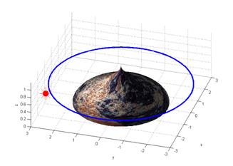
Fig. 7 A simulation scenario for active lighting control
Light source turns off here
![]()
![]()
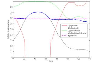
Fig. 8 The simulation results of Iave
In the third run, the global light is always on and the local light is controllable accordingly. With the fuzzy control method, the generated curve of image intensity Iave is illustrated as curve (4) in Fig. 8. The corresponding curve of lighting level is shown as curve (1). This response is quite satisfactory for robot to understand the scene. It is closest to the setpoint although there is no means to reduce the image brightness in the center part (due to the uncontrollable global light source) when we assume all other parameters are fixed in the system. Of course, this problem can be solved if the lens aperture or focus is controllable for a particular system setup. Another point, which should be emphasized here, is that the light source is turned off when its energy level goes below 30% of the maximum output level.
In this research, some other simulation experiments were implemented to verify the control performance with some ideal input signals. The step response, sinusoidal response, zero input response, and random input response of the actively illuminated vision system have been observed, while we assume it has 10% environment light noise. In practice, the step response happens when the robot stays in a dark room and a light is turned on at a certain time. The sinusoidal response is observed when the robot walks in an environment with periodically installed lights, e.g. a robot moving on a road. The random input response simulates some cases in a general natural environment. All these experiments had produced satisfactory results.
B. Robot Manipulation in Real Environments
Practical experiments on a robot system for active lighting control had also been carried out at the University of Hamburg. The mobile robot has an end-effector with 6DOFs for dexterous manipulation. An eye-in-hand camera is used to observe the scene and the active illumination device contains two light sources which can be controlled by a PWM module (Fig. 9). The robot works in many different environments and controls its lighting level automatically.
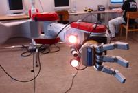
Fig. 9 The active illumination device (one eye-in-hand camera and two light sources controlled by a PWM module)
 ?
?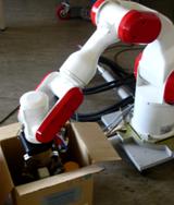
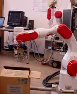
Fig. 10 Experiments of robotic manipulation in a box to test lighting control.
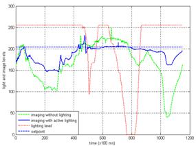
Fig. 11 Robotic manipulation in a box for comparing with and without active lighting control
To compare the performance with or without lighting control, we designed another experiment. The robot has a task to open a closed box and find a target (Fig. 10). The job is repeated twice. In the first experiment, the robot is equipped with the active lighting control system. The robot manipulation trajectory is recorded and repeated exactly in the second experiment in which the conditions, including environmental lighting and target status, are set as the same as that in the first one, but without active local light. The image sequences are computed to evaluate their qualities. The results are illustrated in Fig. 11. In the first experiment, there is a control setpoint (80%). As shown, it is found that the image quality is much better when the robot is equipped with the intelligent lighting control system. The heavy solid line show that brightness is mostly controlled in a good range, i.e. between 150-210.
VII. Conclusion
This paper has presented several strategies of intelligent lighting control for industrial automation and robot vision tasks. It is proposed to achieve good illumination conditions so that high-quality images can be obtained for good understanding of scene contents. Characteristics of the vision camera are analyzed and desirable conditions are defined. The image intensity is controlled at a pre-determined setpoint by a fuzzy controller. The fuzzy interference is suggested because it is an effective way to incorporate human experience or strategies into industrial control systems. By adopting the method, it is expected that poor quality images with either too dark or too bright intensity are avoided by controlling light source energy, the relative position, or the aperture and focus of the lens. Practical experiments were carried out to test the lighting control for robotic manipulation applications. Results show the effectiveness of the proposed approach.
References
[1] W.-F. Xie, Z. Li, et al., "Switching Control of Image-Based Visual Servoing With Laser Pointer in Robotic Manufacturing Systems," IEEE Trans. Industrial Electronics, vol.56, no.2, pp.520-529, Feb. 2009.
[2] I. Morgan, H. Liu, B. Tormos, A. Sala, "Detection and Diagnosis of Incipient Faults in Heavy-Duty Diesel Engines," IEEE Trans. Industrial Electronics, vol.57, no.10, pp.3522-3532, Oct. 2010.
[3] A. Agrawal, Y. Sun, et al., ?/span>Vision-guided Robot System for Picking Objects by Casting Shadows? Int. J. of Robotics Research, vol. 29, no. 2-3, pp.155-173, 2010.
[4] S.Y. Hwang, J.B. Song, "Monocular Vision-Based SLAM in Indoor Environment Using Corner, Lamp, and Door Features from Upward-Looking Camera," IEEE Trans. Industrial Electronics, 2011 (in press)
[5] E. Marchand, "Control Camera and Light Source Positions using Image Gradient Information", IEEE Int. Conf. on Robotics and Automation (ICRA), Rome, Italy, pp. 417-422, 2007.
[6] W.-C. Huang, C.-H. Wu, "Adaptive color image processing and recognition for varying backgrounds and illumination conditions," IEEE Trans. Industrial Electronics, vol.45, no.2, pp.351-357, Apr 1998.
[7] Y. Hu, W. Zhao, L. Wang, "Vision-Based Target Tracking and Collision Avoidance for Two Autonomous Robotic Fish," IEEE Trans. Industrial Electronics, vol.56, no.5, pp.1401-1410, May 2009.
[8] T. Yamazoe, S. Kishi, et al., ?/span>Improved Visibility of Monocular Head-Mounted Displays Through the Bright Control of Backlighting? J. of Display Technology, vol. 6, no. 9, pp. 367-373, 2010.
[9] N. Zuech, "Machine Vision and Lighting", Machine Vision Online, http://machinevisiononline.org
[10] F. Kahraman, M. Gokmen, et al., ?/span>Active illumination and appearance model for face alignment? Turkish J. of Electrical Engineering and Computer Sciences, vol. 18, no.4, pp. 677-692, 2010.
[11] H.-P. Huang, J.-L. Yan, T.-H. Cheng, "Development and Fuzzy Control of a Pipe Inspection Robot", IEEE Trans. Industrial Electronics, vol. 57, no. 3, pp. 1088-1095, 2010.
[12] M. Muehlemann, "Lighting for Color-Based Machine Vision Inspection of Automotive Fuse Blocks", Illumination Technologies, Inc., http://www.illuminationtech.com
[13] Q. Shi, C. Zhang, N. Xi, J. Xu, "Develop feedback robot planning method for 3D surface inspection," IEEE/RSJ International Conference on Intelligent Robots and Systems, pp.4381-4386, Oct. 2009.
[14] T. Eltoft, R.J.P. deFigueiredo, "Illumination control as a means of enhancing image features in active vision systems", IEEE Trans. Image Processing, vol. 4, no. 11 pp. 1520-30, 1995.
[15] J. B. Park, G.N. Desouza, "Analysis of clipping effect in color images captured by CCD cameras," Proc. of IEEE Sensors, pp. 292- 295, 2004.
[16] K. Hara, K. Nishino, K. lkeuchi, "Light source position and reflectance estimation from a single view without the distant illumination assumption," IEEE Trans. Pattern Analysis and Machine Intelligence, vol.27, no.4, pp. 493- 505, 2005.
[17] Y.-F. Qu, Z.-B. Pu, etc., "Design of self-adapting illumination in the vision measuring system", Int. Conf. on Machine Learning and Cybernetics, pp. 2965 - 2969, 2003.
[18] Y. Xu, J. Zhang, "Abstracting human control strategy in projecting light source", IEEE Trans. Information Technology in Biomedicine, vol. 5, no. 1, pp. 27 -32, 2001.
[19] S. Y. Chen, J. Zhang, etc., "Active Illumination for Robot Vision", IEEE International Conference on Robotics and Automation (ICRA), Roma, Italy, pp. 411?16, Apr. 2007.
[20] C.–L. Hwang and C.-Y. Shih, "A Distributed Active-Vision Network-Space Approach for the Navigation of a Car-Like Wheeled Robot," IEEE Trans. Industrial Electronics, vol.56, no.3, pp.846-855, March 2009.
[21] A. Ortiz and G. Oliver, "Radiometric calibration of vision cameras and intensity uncertainty estimation", Image and Vision Computing, Vol. 24, No. 10, pp. 1137-1145, Oct. 2006.
[22] G. Srinivasa, S.J. Koppal, and S. Yamazaki, "Temporal dithering of illumination for fast active vision", European Conference on Computer Vision (ECCV), pp.830-844, Oct. 2008.
[23] W. Chung, S. Kim, etc., "Safe Navigation of a Mobile Robot Considering Visibility of Environment," IEEE Trans. Industrial Electronics, vol.56, no.10, pp.3941-3950, Oct. 2009.
[24] W. Kim, J.T. Kim, ?/span>Effect of Background Luminance on Discomfort Glare in Relation to the Glare Source Size? Indoor and Built and Environment, vol. 19, no. 1, pp. 175-183, 2010.
[25] S. Zhao, B. Liu, Y. Ren, J. Han, "Color tracking vision system for the autonomous robot," 9th International Conference on Electronic Measurement & Instruments, pp.182-185, Aug. 2009.
[26] I. Sato, Y. Sato, K. Ikeuchi, "Illumination distribution from shadows", IEEE Computer Society Conf. on CVPR, pp. 306-312, 1999.
[27] I. Lewin, O. John, "Luminaire photometry using video camera techniques", J. of the Illuminating Engineering Society, v 28, n 1, pp. 57-63, 1999.
[28] S. K. Nayar, K. Ikeuchi, T. Kanade, "Surface reflection: physical and geometrical perspectives", IEEE Trans. Pattern Analysis and Machine Intelligence, vol.13, no. 7, pp. 611-634, 1991.
[29] J. Zhao, X. He, R. Zhao, "A Novel PWM Control Method for Hybrid Clamped Multilevel Inverters", IEEE Trans. Industrial Electronics, vol. 57, no. 7, pp. 2365-2373, 2010.
[30] X. Li, C. Bowers, T. Schnier, "Classification of Energy Consumption in Buildings with Outlier Detection", IEEE Trans. Industrial Electronics, vol. 57, no. 11, pp. 3629-3644, 2010.
[31] H. Liu, D.J. Brown, G.M. Coghill, "Fuzzy Qualitative Robot Kinematics", IEEE Transactions on Fuzzy Systems, vol. 16, no. 3, pp. 808-822, 2008.
[32] J. Jamaludin, N.A. Rahim, W.P. Hew, "An Elevator Group Control System With a Self-Tuning Fuzzy Logic Group Controller," IEEE Trans. Industrial Electronics, vol.57, no.12, pp.4188-4198, Dec. 2010.
 S. Y. Chen (M?1–SM?0) received the Ph.D. degree in
computer vision from the Department of Manufacturing Engineering and
Engineering Management, City University of Hong Kong, Hong Kong, in 2003.
S. Y. Chen (M?1–SM?0) received the Ph.D. degree in
computer vision from the Department of Manufacturing Engineering and
Engineering Management, City University of Hong Kong, Hong Kong, in 2003.
He joined Zhejiang University of Technology in Feb. 2004 where he is currently a Professor in the College of Computer Science. From Aug. 2006 to Aug. 2007, he received a fellowship from the Alexander von Humboldt Foundation of Germany and worked at University of Hamburg, Germany. From Sep. 2008 to Aug. 2009, he worked as a visiting professor at Imperial College, London, U.K. His research interests include computer vision, 3D modeling, and image processing. Some selected publications and other details can be found at http://www.sychen.com.nu.
Dr. Chen is a senior member of IEEE and a committee member of IET Shanghai Branch. He has published over 100 scientific papers in international journals and conferences. He was awarded as the Champion in 2003 IEEE Region 10 Student Paper Competition, and was nominated as a finalist candidate for 2004 Hong Kong Young Scientist Award.
 Jianwei Zhang (M?2) received
both his Bachelor of Engineering (1986, with distinction) and Master of
Engineering (1989) from the Department of Computer Science of Tsinghua
University, Beijing, China, and his PhD (1994) at the Institute of Real-Time Computer Systems and Robotics, Department of Computer Science, University of
Karlsruhe, Germany.
Jianwei Zhang (M?2) received
both his Bachelor of Engineering (1986, with distinction) and Master of
Engineering (1989) from the Department of Computer Science of Tsinghua
University, Beijing, China, and his PhD (1994) at the Institute of Real-Time Computer Systems and Robotics, Department of Computer Science, University of
Karlsruhe, Germany.
Jianwei Zhang is professor and head of TAMS, Department of Informatics, University of Hamburg, Germany. His research interests are multimodal information systems, novel sensing devices, cognitive robotics and human-computer communication. In these areas he has published over 250 journal and conference papers, technical reports, four book chapters and two research monographs. He has received several awards, including the IEEE ROMAN Best Paper Award in 2002 and the IEEE AIM Best Paper Award 2008. Dr. Zhang is member of organization committee of numerous international conferences, including some future ones such as IEEE ICRA 2011 Program Co-chair, IEEE MFI2012 General Chair, IROS 2015 General Chair, etc.
 H. X. Zhang (M?4) received Ph.D. degree in
Mechanical and Electronic Engineering from Beijing University of Aeronautics
and Astronautics, China, in 2003. From 2004, he worked as Postdoctoral Fellow
at the Institute of Technical Aspects of Multimodal Systems (TAMS), Department
of Informatics, Faculty of Mathematics, Informatics and Natural Sciences, University of Hamburg, Germany.
H. X. Zhang (M?4) received Ph.D. degree in
Mechanical and Electronic Engineering from Beijing University of Aeronautics
and Astronautics, China, in 2003. From 2004, he worked as Postdoctoral Fellow
at the Institute of Technical Aspects of Multimodal Systems (TAMS), Department
of Informatics, Faculty of Mathematics, Informatics and Natural Sciences, University of Hamburg, Germany.
Dr. Zhang joined the Department of Technology and Nautical Sciences, Aalesund University College, Norway in April 2011 where he is a Professor on Robotics and Cybernetics. The focus of his research lies on mobile robotics, especially on climbing robots and urban search and rescue robots, modular robotics, and nonlinear control algorithms. In these areas, he has published over 70 journal and conference papers and book chapters as author and co-author. Recently, he has received the best paper award at the IEEE/AEME AIM2008 conference, and three finalist awards for best conference paper at IEEE Robotics and Automation conferences.
 N. M. Kwok (M?0) received the PhD degree in robotics from the
University of Technology Sydney, Australia, in 2007.
N. M. Kwok (M?0) received the PhD degree in robotics from the
University of Technology Sydney, Australia, in 2007.
From 2005 to 2008, he was a research fellow in the University of Western Sydney and the University of Technology Sydney. He joined the University of New South Wales in 2008 as a Lecturer in the School of Mechanical and manufacturing Engineering. He has published about 100 journal and conference articles. His research interests include image processing, intelligent computation and robotics.
 Y. F. Li (M?1–SM?1) received
the Ph.D. degree in robotics from the Department of Engineering Science,
University of Oxford, Oxford, U.K., in 1993.
Y. F. Li (M?1–SM?1) received
the Ph.D. degree in robotics from the Department of Engineering Science,
University of Oxford, Oxford, U.K., in 1993.
From 1993 to 1995, he was a Postdoctoral Research Associate in the Department of Computer Science, University of Wales, Aberystwyth, U.K. He joined City University of Hong Kong, Hong Kong, in 1995 where he is currently an Associate Professor in the Department of Manufacturing Engineering and Engineering Management. His research interests include robot vision, sensing, and sensor-based control for robotics. In these areas, he has published over 100 papers in international journals and conferences. He was an associate editor of IEEE Transactions on Automation Science and Engineering (T-ASE).